![]()
![]()
![]()
|
|
|
The 147.315 is Not an SFFMA repeater, but many of us use it, so I have added it here. Specifications:
Last status report on this repeater: In maybe a new record for me, the 147.315 is fixed. I repaired the repeater on the bench as described here: (below) We installed it tonight and it was making power. While it's designed for 100 watts, we could make 140, so it has plenty of head room. I set it at 90 watts. One false alarm due to a cross threaded connector, but we found that fast. I'm going to run it a little hotter because it ends up that every GPS seems to put out a carrier RIGHT on 147.315 MHz. A bit more power will help minimize the interference. I got a weak, but usually readable signal from Don, KF4CUP, on a handheld and rubber duck at US 27 and Johnson Street in Broward. The repeater was full scale on his radio there. That looks like about 20 miles handheld range. I added a new filter and replaced some jumpers in an effort to minimize the de-sense we get from the County paging transmitter on 151.1 MHz. Unfortunately, the interference is still very strong. Its really hard to get rid of a 1kW transmitter signal so close (3.185 MHz) to the input frequency. Sort of like trying to hear a whisper at a loud rock concert. A strong station using the 147.315 repeater will get some static when the paging transmitter comes on. A weak signal get wiped out of the repeater for a few seconds. The transmissions are short, so just asking for a repeat is usually enough. We'll keep trying things to get the receiver better. But in the meantime, the transmitter is better now. Ray, KD4BBM
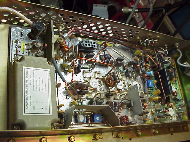
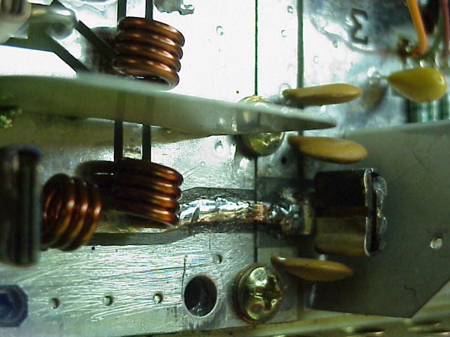
GE Mastr II Power Amp Repair Here are some pictures from inside the Power Amp before and after a recent PA repair. The symptoms were weak signal. It tested at about a 1/10th a watt. But the power supply voltage dipped from 15 to 13 volts when the PTT was applied. So the PA seemed to be drawing current. Normal current draw with weak output means the transistors haven't blown yet, but the RF isn't getting out. This is a very common failure mode for this PA. Inside the 100 Watt PA. To make things more visible while on the bench, the PA is upside down from what you're used to.
The problem is very common to the Mastr II repeater PAs. A solid jumper breaks between the PA board and the harmonic filter (box in the lower left in the picture above.) Look for a tiny crack in the solder between the two screws.
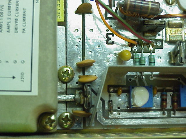
With the cover of the harmonic filter removed:
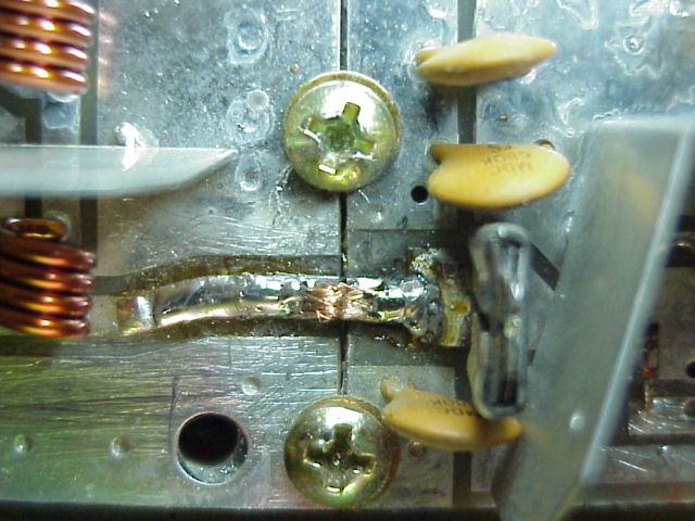
The crack is more visible here. I found a small strip of metal under the solder that had been used to jump between the boards. It worked for a while, but it eventually failed at the right end of that metal strip. There was pitting between the bottom of the strip and the PCB land on the board on the right.
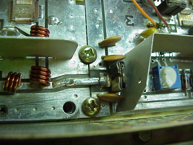
Here's a close up of the same jumper after the repair. It's hard to see from above, but there's a small jumper of solder wick in a little hump, like a small upside down U. The hump is still flexible since the solder is on both ends, but didn't suck into the middle. You can use needle nose pliers on the middle to act as a heat sink to keep the center too cold to draw in solder. Now when the boards expand and contract, the flexible gap will flex without breaking. The upside U needs to be small or it could act like an inductor. Don't go any wider than the existing circuit board traces or that could also effect the impedance. After this picture, I cleaned up the excess flux.
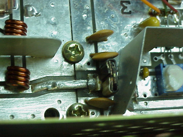
Here's a view from the side to give you some idea of the height of the jumper. It's more of a ripple than a hump.
After this modification, the Amp could make up to 140 watts. It was set to 90 watts. My thanks to Chris Jensen for his help with the troubleshooting, removal and installation of the Power Amp. Ray, KD4BBM
Additional Suggestions from the mailing lists: Ray, The problem you and many others have experienced is expansion / contraction of the PC boards that eventually causes the crack you documented. One additional modification that I have found quite helpful is to add washers under the two adjacent screws and then solder the washers down to both the PA and filter boards while the screws are backed off (loosely left in place to 'locate' the washers). This modification holds the distance between the PA and filter boards constant over temperature thus relieving the mechanical stress placed on the jumper. Ed Yoho 07/15/03 |
|